 Hot Buzz
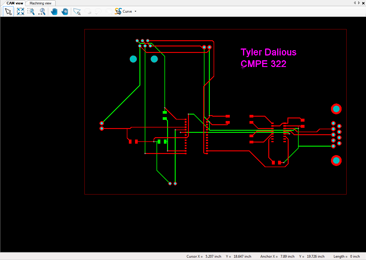
The Hot Buzz is the first student-made project to be fabricated from our own lab on the university campus. The design developed through the use of OrCAD and the Cadence PCB Editor. A footprint was carefully laid out for the PIC24 chip and the process from design to schematic progressed quickly.
With the proper instruction, a sheet of copper went through a process from milling to part placement. The first milling step was to create holes for through-hole components. Following that the electro-plater filled the vias and pin holes with copper. Then, once properly cleaned, the traces and pads were milled. After a close 100% inspection of the traces along with continuity checks the parts were soldered to the board.
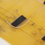
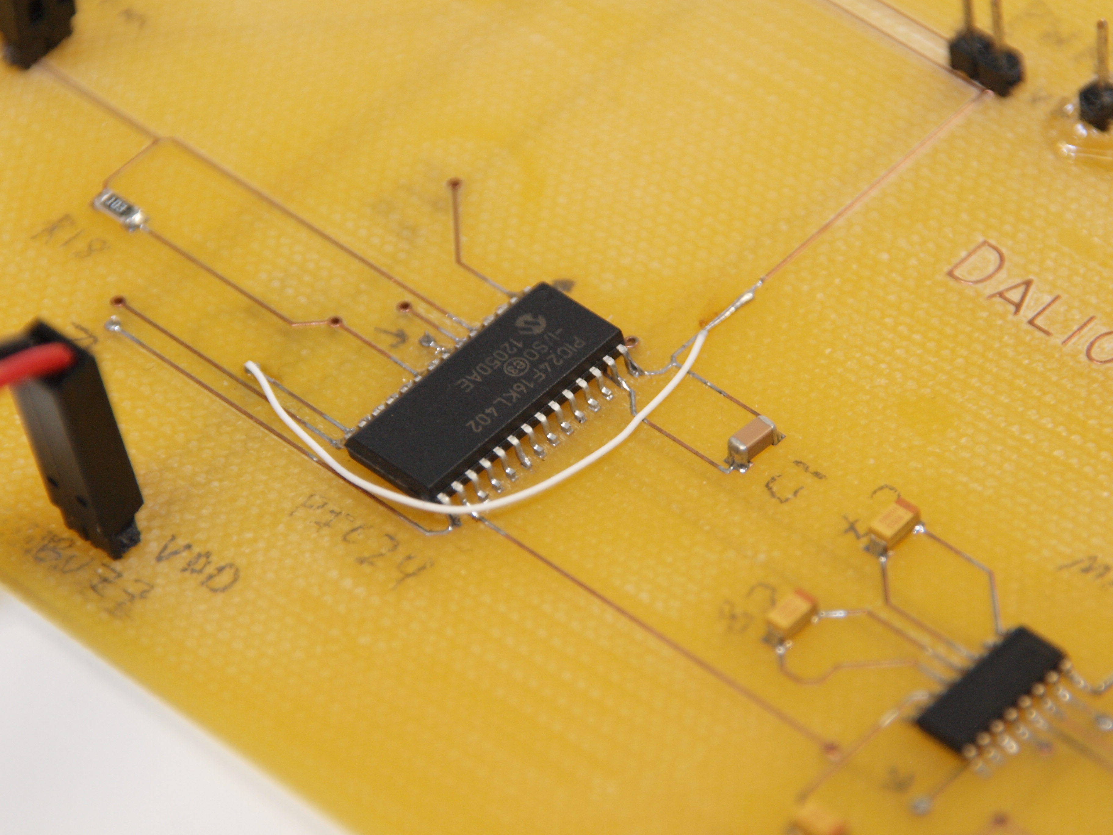
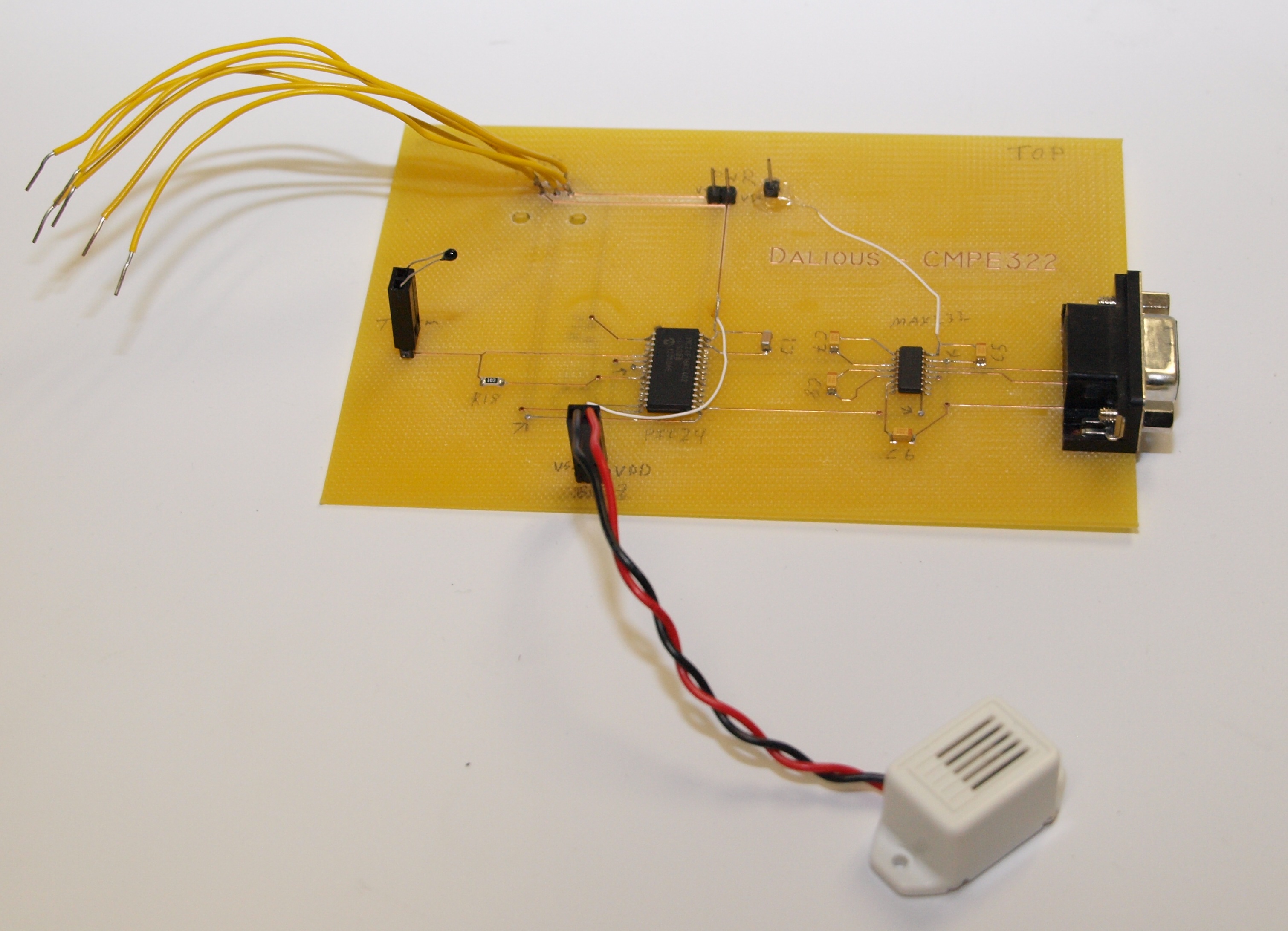
The Hot Buzz uses a PIC24 as its main micro-controller with a MAX232 chip for the UART communication. The three AAA batteries have enough voltage to power both the MAX 232 and the PIC24 at the same time. All components are surface mount devices (SMD) except for the RS232 serial connector, the thermistor, the buzzer, and the power connection. The thermistor and buzzer were left replaceable with the intention of future case design modification.
The device scales the temperature read by the sensor to a level between 0 and 8. Once a designated threshold is reached, the buzzer sounds. The threshold can be changed and the temperature level can be monitored, both through the use of a serial connection. Three AAA batteries power the device.
Of the skills needed to complete this project, those which were found most useful were OrCAD design, analysis, and problem solving as well as 100% inspection.

Find my GIT repository containing project code and OrCAD files HERE.